
 By
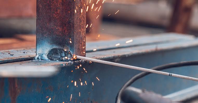
If a structural weld fails, it makes a low sound. It fails while under strain, frequently without notice, and the results can be anything from costly rework to the complete failure of a structure. Good welds aren’t subjective based on how they look or the experience of the operator – these are determined by the science of metallurgy, physics, and the adherence (or lack of adherence) to proper procedures.
Base metal compatibility and surface preparation
The quality of the metal surface before welding significantly affects the properties of the welding joint. If the metals are not compatible enough, the finished deposit will not bond properly at the microscopic scale, leading to a weaker joint that can easily fail under load. One of the quickest ways to achieve such a joint is to pair a different metal alloy with an improper welding technique that has not been previously certified to show that it can create strong and reliable bonds.
Another common mistake that can be often observed in practice is to not take surface preparation seriously. Some of the most common sources of contamination in welding are the mill scale on the base metal, any form of rust, moisture, or oil/hydrocarbon residues from cutting or lubricating the metal. If there’s moisture or organics, there’s hydrogen production in the arc. Unlike weld pool contaminants that can be diluted and washed out, hydrogen becomes part of the molten metal pool and is distributed through the crystallizing metal – that’s what makes it so dangerous, greatly reducing the metal’s ductility and resistance properties.
Selecting the correct consumable chemistry
The choice of filler metal is more than simply determining which wire or electrode will do the job. The filler metal’s tensile strength and yield strength must match or exceed the mechanical properties of the base metal, but its toughness at the operating temperature and its ductility under cyclic loading should also be considered. When it comes to structural steel, the matching principle applies as a rule of thumb: when welding ASTM A36 steel, for example, the filler metal is classified based on the base metal being welded. Requirements are for equivalent or superior tensile strength. If the filler metal is weaker than the base, the joint will be the weak link.
The second consideration is the filler wire diameter. Most shops use a single size for most applications, based on the best speed and deposition rates rather than considering how the small bead will affect the quality of the finished weld. The wire too big for the joint or the material and an excessive heat input results, affecting bead shape and increasing spatter. The wire too small and the amperage is too low to produce proper fusion. If a change must be made, the wire ends must be clipped and discarded.
Selecting the right welding wire grade and diameter for the specific base metal and joint configuration is the primary focus for achieving the required tensile strength and ductility in MIG and flux-cored structural applications.
Precise control of heat input and cooling rates
The amount of heat added to the plate material at the point where welding occurs is a key factor virtually defining the strength of the bond. When the melting point is approached, the metal begins to lose its internal strength and it becomes more challenging for the atoms to retain their structure. Insufficient heat reduces the metallurgical bond too.
Simply put, a weld where the iron atoms on one side of the fusion line have never mixed with the iron atoms on the other side is not as strong as one where they have. This can happen either because not enough heat is applied to make them mobile, or because they cool and become immobile before they have a chance to mingle.
For thick structural steel sections, pre-heating is a code requirement for a reason. When heavy plate is welded cold, the mass of the surrounding metal conducts heat away from the joint very quickly. Rapid cooling in hardenable steels produces martensite – a hard, brittle microstructure that’s particularly susceptible to hydrogen cracking. Pre-heating slows the cooling rate, keeps the HAZ in a tougher phase, and gives dissolved hydrogen more time to diffuse out before the metal becomes rigid.
Interpass temperature control matters too. Allowing a multi-pass weld to cool excessively between passes, or conversely letting it accumulate heat without restriction, both affect the final mechanical properties in ways that aren’t visible to the eye.
The role of shielding gas flow and composition
The molten weld pool is very reactive at welding temperatures. It easily combines with the oxygen and nitrogen in the air to create porosity and inclusions, at the same time reducing the overall strength and toughness of the welded joint. The shielding gas protects the weld pool from this contamination.
For instance, MIG welding structural carbon steel, 75% Argon / 25% CO2 is a common shielding gas. It provides a good balance of stability, penetration, and minimal spatter production. While Pure CO2 offers deeper penetration at a lower cash cost, it produces less stable arcs and more spatter. Increasing the Argon ratio enhances the welding arc but could decrease penetration in thicker areas.
Flow rate is one of those things that tends to go out the window in the hurly-burly of production work. Too low and you won’t control the weld pool environment – particularly in a cross-draft. Too high and you can actually be sucking air into the area you’re welding! The right flow rate is pretty specific to the nozzle size, joint geometry, and shop conditions. Change these and your flow rate might need to change as well.
Commonly, it often gets left where the nozzle cleaning drill gets put and that is just bad practice. If you don’t know why the flow rate is set to 20 CFH, you have no idea if that’s suitable for your situation. It can be a source of defects in its own right if, for instance, the previous job required a higher flow of different gas and nobody switched it or re-labeled the cylinder. Always check your cylinder contents against your work order before you light up a production run.
Joint geometry and fit-up precision
Joint geometry defines how load stresses distribute across the weld cross-section and how accessible the root of the joint is to the welder. AWS D1.1 and equivalent structural codes specify joint geometries for good reason: they’re the result of extensive testing and represent designs that produce reliable, inspectable welds when executed to tolerance.
Poor fit-up forces operators to compensate. An excessive root opening means the welder is bridging a gap rather than fusing two prepared faces, which tends to produce a weaker, more variable root pass. An inconsistent bevel angle changes the heat input required along the length of the joint. Misalignment creates areas where one plate is thicker at the joint than the other, which changes penetration depth and produces stress concentrations at the transition.
Over-welding – depositing more weld metal than the joint design requires to compensate for poor fit-up – increases residual stress and distortion without improving joint strength. It also adds direct cost in materials, time, and post-weld correction.
Fit-up should be checked dimensionally before welding starts, not after the first pass reveals a problem.
Welder technique and parameter settings
Voltage, amperage, wire feed speed, travel speed, and torch angle all work together to develop a specific bead geometry and penetration profile. If you change one of these, the others will need to adjust accordingly. Welding Procedure Specifications (WPS) are designed for this purpose: they establish the parameter window in which the desired mechanical properties can be attained, and this has been proven by tests, not by guessing.
Travel speed is extremely delicate. If it’s too fast, you will obtain a narrow, high-crowned bead with low fusion on the sidewall. If it’s too slow, heat input increases, the heat-affected zone (HAZ) widens, and the bead is wide, flat, and likely to overlap at the toes. The torch angle decides where the arc force is directed – just a few degrees off from the specified stringer or weave technique and the penetration will shift asymmetrically across the joint.
Undercutting at the weld toes, overlapping where the bead misses melding into the base metal, surface porosity – defects caused by poor technique can all be seen with the eye. The results of marginal parameters rather than clearly wrong ones will only be uncovered by non-destructive testing.
Post-weld inspection and quality assurance protocols
Welding imperfections and subsequent rework constitute to a significant portion of the total cost of fabrication jobs. The more fiscally responsible alternative is a systematic quality assurance program that uncovers issues as they happen.
Visual inspection is the first and most available tier. It verifies that the surface meets the acceptance criteria in the code and necessary standards and specifications, for such characteristics as surface cracks, undercut depth, overlap, surface porosity, and bead profile. But it is only skin deep.
For mission-critical load-bearing joints, non-destructive testing bridges that observational gap. Ultrasonic testing uses sound wave reflection of the test object’s back wall (calibrated block) to locate internal discontinuities without disturbing or destroying the weld. Radiographic testing of the weldment exposes a film and develops a radiographic image that reveals volumetric defects. Magnetic particle testing employs a magnetic field to detect surface and near-surface flaws in ferromagnetic materials.
Which NDT method suits the particular job at hand depends on the joint, the material, and the code requirements for the application. The larger point: this isn’t a trivial administrative task. It’s the verification step that confirms the production work was done properly and the joint will perform as engineered.
Managing residual stresses and distortion
Welding heats metal locally and rapidly. The surrounding material constrains that heated zone as it tries to expand, then as it contracts on cooling. The result is a complex field of residual stresses locked into the structure – compressive in some areas, tensile in others.
Tensile residual stresses are the concern, because they add to service loads and can reduce the fatigue life of the joint. In thick, heavily restrained sections, they can also contribute to stress corrosion cracking in certain environments.
Distortion is the visible consequence of the same thermal cycle. Controlling it means thinking about weld sequence before production starts. Backstep welding, where individual passes are deposited in the opposite direction to the overall weld progression, reduces the cumulative distortion in long weld runs. Balanced welding on symmetric joints – alternating passes on each side of a flange, for example – keeps the structure pulling against itself rather than bending progressively in one direction.
Where residual stress levels are a design concern, post-weld heat treatment can reduce them. The assembly is heated to a specified temperature, held long enough for stress relaxation to occur uniformly, then cooled at a controlled rate. It adds process time and cost, but for certain applications it’s the only way to meet the stress state requirements of the design.
Quality in structural welding isn’t something you inspect in at the end. It’s built in through compatible materials, correct consumables, disciplined procedure compliance, and systematic verification – every time.







Comments